by Roger Hultquist, Orbetron, and Hank Gray, Mahr Metering Systems
Combining liquids with powders is a delicate task, as the material must be added at precise times and in the appropriate amounts to achieve the correct end-product quality. Continuous, inline meter mixing of the materials has proven to create a well-blended mixture. This article discusses different techniques for continuous, inline meter mixing of liquids and bulk solids.
Over the years, many manufacturers’ operations have converted from batch processing of liquids or bulk solids to continuous or on-demand mixing. Continuous mixing provides many advantages, such as savings in labor, smaller processing machinery, less power consumption, better accuracy, less waste production and disposal, and reduced floor space requirements. In today’s processing environment, a multitude of companies are looking at the more complicated process of adding both liquid and bulk solid materials into a continuous mixing process. The following is a brief discussion about different techniques and options to consider when continuously mixing liquids and bulk solids.
There are continuous solutions for liquid-only mixing, generally called meter-mix-dispense systems (MMDs), and for bulk-solids mixing, generally called continuous volumetric or gravimetric blenders. For processes needing to add bulk solutions to liquids, the continuous processing equipment available is still leaning heavily toward batch mixing designs. But technologies are emerging that incorporate the process technologies of both MMDs and continuous blenders, allowing for inline liquid and bulk solids mixing.
Metering Liquids Continuously
Liquids have many advantages over bulk solids when metering and measuring. A liquid’s physical nature allows it to fill volumes evenly, with very stable and predictable density. This results in greater volumetric accuracy with several types of positive-displacement (PD) pumps, which can then easily be enhanced with added measurement options using flow meters or load cells for gravity measurement. When designing a liquid metering and mixing system, the metering device and measurement device are crucial.
- Metering Device. Many pump types, such as centrifugal, turbine, diaphragm progressing cavity, and gear pumps, transfer liquid. However, for predictable metering, PD pumps, such as gear and progressing cavity pumps, are usually preferred due to their close, direct, and generally linear relationship between pump speed and volume displacement. This makes the metering process more predictable, easily calibrated, and controllable. PD pumps are dependent on several aspects of the liquid and process itself, such as differential pressure, flow rate, operating temperature, chemical compatibility, shear issues, fillers, viscosity, and sometimes density. Most PD pumps meet a few or even many of those requirements, but not at all. It’s especially important to make sure the pump can simply handle the liquid before giving any consideration to the pump’s accuracy and performance in the mixing process.
- Measurement Device. Measuring the liquid inline flow for a mixing system can be handled via volumetric measurement or liquid flow measurement.
The first and simplest way to measure the liquid inline flow is with volumetric measurement. This relies on the volumetric accuracy measured by time or pump rotations to meter the right liquid amount into the mixing process. Rotational speed can be monitored and optimized with a speed pickup device or tachometer, but the accuracy is still fixed to the pump’s performance. Measurement is based on the rotation of the pump motor or a simple time measurement. Both are compared to a volume pumped per period of time or per rotation.
The second way to measure liquid inline flow is via a liquid flow. Liquid is a straightforward state to measure through a tube or pipe. This measurement is continuous, inline, and can work well in a bathing or continuous mixing application. Several different flow meter styles are available, and like PD pumps, you can select the best one for your application based on the liquid characteristics and conditions being measured. Liquid flow meter styles include but aren’t limited to gear, Coriolis, turbine, and ultrasonic. - Measuring Bulk Solids Continuously. Since many articles have been published in PBE about metering bulk solids, we won’t delve into this subtopic. Suffice it to say that the metering needs to be consistent and measurable to ensure a correct overall mixture.
- Metering Device. Many feeder types can meter bulk solids. For metering bulk solids continuously, the feeder selection will depend on the material characteristics. Bulk solids feeder types include but aren’t limited to disc, single-screw, twin-screw, belt, vibratory, and rotary airlock. The feeder type selected should produce a predictable volumetric flow that can then be easily improved through speed or flow control via flow measurement or, more typically, using load cells or balances.
- Measurement Device. Measuring the bulk solids inline flow for a mixing system can be handled via volumetric measurement or gravimetric control.
Just like with liquid measurement, the first and simplest way to measure bulk solids inline flow is via volumetric measurement. This relies on the volumetric accuracy measured by time or feeder rotations to meter the right bulk solids amount into the mixing process. Rotational speed can be monitored and optimized with a speed pickup device or tachometer, but the accuracy is still fixed to the feeder’s performance. Measurement is based on rotations of the feeder motor or a simple time measurement. Both are compared to a volume fed per period of time or per rotation.
The second way to measure bulk solids inline flow is via gravimetric control, which relies on constant weight measurements to improve the flow’s volumetric accuracy to meter the correct bulk solids amount into the mixing process. Bulk solids are more limited in trying to use inline flow meters. Gravimetric control is a simple and accurate way to measure feed rate and make small adjustments to correct errors. Gravimetric measurement is essentially a continuous, inline measurement and can work well in a continuous mixing application. Load cell configurations include platform scales, single- and multiple-point load cells, and balances for lower rates.
Mixer Considerations
The liquids and bulk solids combination is handled using one of several different methods, depending on the characteristics of the materials being mixed. As previously noted, a continuous measuring process must be in place to monitor the flow of the liquid and bulk solids before you consider the inline mixing process, the mixer must be designed to handle the characteristics of the materials being mixed.
Two inline mixer types are suitable for mixing bulk solids and liquids- low-pressure dynamic mixers (LPDMs) and vertical dynamic mixers (VDMs).
Figure 1:
A low-pressure dynamic mixer (LPDM) is designed to accept solids in the top inlet and incorporate the liquids one or two screw flights down the barrel from the solids inlet.
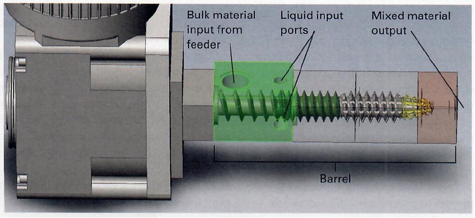
Low-Pressure Dynamic Mixer
An LPDM looks like a mini single-screw extruder, as shown in Figure 1. The mixer doesn’t use heat and isn’t designed to create a reaction within its housing. An LPDm is designed to accept solids in the top inlet and incorporate the liquids one or two screw flights down the barrel from the solid’s inlet. The mixer can be assembled with different screw sections to impart more compression, shear, and transfer. The key to the continuous addition of the bulk solids is the first few screw flights. The tolerance between the screw’s flights and inside diameter is crucial to keeping both the bulk solids moving forward toward the liquid injection point and the injected liquid moving forward and not slipping backward in the screw to the bulk solid’s entry point.
Beyond the bulk solids and liquid inlets, the tolerance between the rotor and the housing inside diameter determines the amount of shear imparted to the mixture and also the mixture’s ability to assist in propelling the mixture downstream to the next process step. The unit is designed to accept the liquid through ports in the barrel’s side under pressure, control the flow through the mixing stages, and assist the pump in evacuating the mixture to the next process step. This next stage can be feeding into a mold or container. In most applications with liquid viscosities greater than 500 centipoise (cP), an LPDM and liquid and liquid pumps can move the mixture a significant distance downstream to the next process step. The equipment’s limitation occurs if a longer downstream movement of the mixture causes the back pressure in the barrel to increase. This can cause the liquid injection in the LPDM to slip and move backward in the barrel toward the bulk solid’s inlet. If you expect a higher back pressure, using a longer bulk solids inlet screw section with more flights will increase the number of sealing lines between the bulk solid’s addition and the liquids addition.
In one case, a customer needed to inline mix a liquid resin with either an alumina powder or a very light-density, easily aerated powder. The liquid flow rates were very low, in the range of 10 to 100 cc/min. The powders were added with a loss-in-weight twin-screw feeder that gravity-fed the powder directly to an LPDM’s top inlet. The LPDM’s inlet was fully open and tangential to the screw rotation, allowing the flights to take in the maximum powder amount. The LPDM screw feed rate by volume was higher than the powder feeder, so the LPDM took all the powder fed to the inlet. (The LPDM screw must always be sized to accept more bulk solids than the feeder is providing; otherwise, the material would back up into the bulk solids feeder.) The inlet screw section was designed with a mass-flow geometry to condense the powder and allow any air to evacuate before the liquid was added. The tolerances between the screw flights and the mixer barrels inside diameter were tight to reduce any powder or liquid slippage back into the powder’s inlet.
The liquid was injected under low-pressure using a precision gear metering pump into the mixer barrel’s side to directly interact with the powder filling the screw flights. The liquid injection rate was directly tied to the required liquid-to-powder weight ratio. The liquid metering was in a recirculation loop, pumping at the required rate from a day tank, through the precision gear pump and mass-flow meter to a three-way valve back into the day tank. When the three-way valve switched from recirculation to dispense, the liquid flow was directed into the LPDM inlet port and was immediately at the set ratio and rate for the powder amount being added into the mixing screw. The mixture moved through the screw’s mixing and shearing section and then to a transfer section. The screw’s ability to pump the mixture, along with the added pressure provided by the precision gear pump, allowed the mixture to be moved several feet into a downstream processing tank.
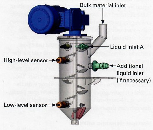
Figure 2:
A vertical dynamic mixer doesn’t generate any pressure, but relies on gravity and agitation or a transfer pump to move the mixture directly into the next process step.
Vertical Dynamic Mixer
A VDM provides more-intensive, non-pressure mixing than an LPDM but can impart much higher shear for a wider variety of bulk solids. Gravity is important in VDM mixing since, unlike LPDMs, a VDM doesn’t generate any pressure. The mixer either uses gravity and agitation to evacuate the mixture directly into the next process step, or must depend on a transfer pump that’s capable of moving a liquid with potentially abrasive particles as fine as powders or as coarse as sand. All materials are added into the mixer at no pressure. The bulk solids and liquids need to be added in very specific areas of the mixer body, and then liquids are added just below the solids stream to ensure that the solids are pre-wetted as they fall into the mixture’s dynamic portion. Speed, blade changes, flow direction, and side sweeping attachments allow a VDM to incorporate very-low-density powders while also being capable of adding high-density minerals such as alumina or sand.
Control of the mixer is critical to the addition of the materials to be mixed. The liquids are run in a recirculation mode so that they’re at the proper flow rate and ready to be at the set ratio with each other and the solids being added. The solids flow must be controlled via an on-off design and ready to run at the set rate almost immediately. A level sensor system within the mixer’s body regulates the material level to keep the point of interaction between the liquids and powders consistent inside the mixer housing. The material discharge can be controlled in one of three ways:
- an on-off value tied to the requirements for the mixture downstream,
- a transfer for a metering pump capable of pumping a bulk solids-filled liquid to the next process step, or
- a simple adapter fitting to restrict and control the mixture’s gravity flow out of the mixer’s bottom.
Based on the mixture type being produced, the pumps and feeders can be controlled by a continuous level sensor in the mixer, which adjusts each device’s flow rate to match the change in the mixer’s level. A simpler control option is an on-off control, in which the total flow of all components is much higher than the mixture amount needed at the mixer’s output. In this case, a low-level signal will start the continuous flow of unmixed liquids and solids until the high level in the mixer is reached. While continuous when running, the controls mimic continuous batching.
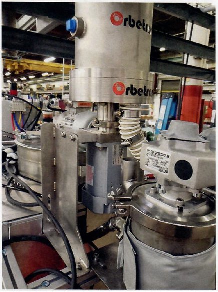
A recent application required the addition of silica sand to an epoxy-hardener mixture. The silica was used to help displace the amount of the expensive epoxy needed to fill large-volume forms. The silica granulates were large and very abrasive. A VDM similar to the one in Figure 3 was used to mix the silica with the liquids with the least amount of handling possible.
Figure 3:
Bulk solids and liquids need to be added in specific areas of a vertical dynamic mixer body, with bulk solids added at the highest point in the mixer body and liquids added just below the solids stream.
The silica was added into the VDM’s upper section aligned just above the epoxy, which together made up almost all the material being mixed. The hardener was added at the same level as the epoxy, but radically opposite the epoxy in the sidewall of the mixer body. The silica was added using a large disc feeder rotating very slowly to lessen the abrasive effect on the feeder components. The epoxy and hardener were metered into the VDM using precision gear pumps. The materials were set up in a dispensing-recirculation process in which both liquids were constantly recirculated at the correct pumping rate using control feedback from a flow meter and diverting the flow back to a day tank using a three-way value.
Two single-point level sensors were used in the VDM’s sidewall to control the start of the inline mixing, the addition of all three ingredients, and the pausing of the addition when the mixer was full of mixed materials.
The mixing arrangement for the silica sand to be incorporated into the epoxy-hardener mixture was a central shaft with radically mounted paddles that could be rotated and locked in a downward-flow or upward-flow position. This allowed operators to adjust how aggressive the upward-pumping or downward-pumping would be. The paddles were also set in alternate up-and-down pumping configurations to keep the material from moving downward too quickly and allow for more shearing and mixing as gravity moved the material downward towards the discharge. The gap between the paddles and the mixer housings inside diameter could also be adjusted. In the case of a thick liquid-bulk solids mixture, the gap was kept fairly open (greater than ¼-inch) to minimize jamming and abrasion while still shearing and mixing the material.
The mixer’s design took the ease of material flow into consideration. The mixing tank had a shallow conical bottom and a 1-inch-diameter opening to restrict flow out of the mixer. The molds to be filled were placed directly under the mixer’s discharge, and the mixture was able to freely flow out via gravity. The rate with which the material flowed out of the mixer could be easily overtaken by the addition rate of the silica and the two liquids. This setup resulted in a simple stop-and-start operation, in which the feeder could simply stop feeding the bulk solids and the silica and the two liquids. This setup resulted in a simple stop-and-start operation, in which the feeder could simply stop feeding the bulk solids and the liquids could be switched from dispensing to recirculation until commanded by the level sensor controls to dispense again.
With the right selection of transfer pump, such as a peristaltic pump, the material could be fed limited distances to an alternate filling station. The limits, in that case, were high due to the silica’s particle size and extremely abrasive nature. In this pumping configuration, the peristaltic pump would use the mixer tank as a surge tank for the mixed material. The mixing controls would again be set up with the capability of overtaking the rate at which the pump could take mixed materials away.
Inline mixing of liquids and bulk solids can be a tricky engineering and processing challenge. Starting with a complete analysis of the materials to be mixed will result in a better selection of the bulk solids feeding and the liquid metering equipment to be used. Then, the selection of an LPD- or a VDM-style inline mixer can follow. Both inline mixer styles can be modified to suit the bulk solids and liquids characteristics. How the mixing fits within the overall process and the following downstream equipment will further refine the proper equipment selection to ensure consistent and continuous inline production of fully mixed liquids and bulk solids on-demand with little to no over mixing, waste, disposal, or time losses.